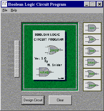
Simple drag drop circuit design makes building a circuit simple..
This program was developed as an end of semester project in
Visual Basic. It combined many of the techniques learned
throughout the semester, to produce a finished product. 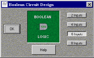
The basic function of the program is to test digital circuits. Two forms make up the entire program. The first is the main page (Boolean Logic Circuit Program) where the visual circuit is displayed, and the startup routine. The second is the Boolean Circuit Design page form where the user selects the number of inputs to use (2, 4, 6 or 8). Each form contains a help section to explain how to use the program.
When the user clicks on the "Design
Circuit" button, the second form pops up, and waits until a
selection for number of inputs is made. When the number of inputs
is selected, and "OK" is selected, the program returns
to the main form.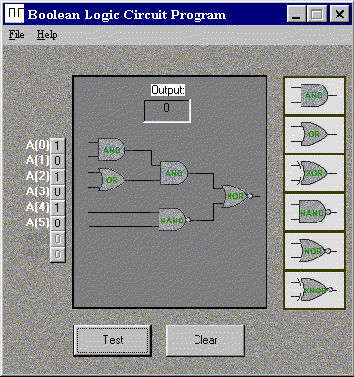 Upon returning to the main
form, a number of empty boxes has shown up, enough to seat the
number of Two-input logic gates to form a single output, based on
the number of inputs chosen. With an option of 6 different gates
to choose from the user can build the circuit by dragging and
dropping gates from the toolbar at the side of the screen. Inputs
can be set by toggling pushbuttons on the left side of the
screen. The circuit can then be tested to find out the output
based on the input conditions.
Upon returning to the main
form, a number of empty boxes has shown up, enough to seat the
number of Two-input logic gates to form a single output, based on
the number of inputs chosen. With an option of 6 different gates
to choose from the user can build the circuit by dragging and
dropping gates from the toolbar at the side of the screen. Inputs
can be set by toggling pushbuttons on the left side of the
screen. The circuit can then be tested to find out the output
based on the input conditions.
The Boolean Logic Circuit Program was designed for a user who has a basic knowlege of Digital logic.
Return to My Home Page